Architectural Concept & Requirements
The structural engineering journey begins with preliminary design and feasibility studies, where engineers work closely with architects and developers to establish the viability of proposed developments. This phase involves initial structural system selection, preliminary sizing of structural members, foundation system evaluation based on soil investigation reports, and cost estimation for various structural options. Engineers must consider factors such as site constraints, adjacent structures, underground utilities, and future expansion possibilities while developing conceptually sound and economically viable solutions.
During feasibility studies, structural engineers conduct preliminary load assessments, evaluate different structural systems (moment frames, braced frames, shear walls, outriggers, etc.), and provide recommendations on the most suitable approach based on building height, usage, architectural requirements, and budget constraints. This phase also involves coordination with geotechnical engineers to understand soil conditions and determine appropriate foundation systems, whether shallow foundations, deep pile foundations, or specialized solutions like raft foundations or basement retaining structures.
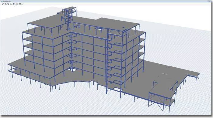
The detailed design phase represents the core of structural engineering work, where comprehensive analysis and design calculations are performed to ensure structural safety and serviceability. This phase involves sophisticated computer modeling using software such as ETABS, SAP2000, SAFE, or STAAD.Pro to analyze complex three-dimensional structural systems under various load combinations. Engineers must consider dead loads, live loads, wind loads, seismic loads (where applicable), temperature effects, and construction sequence loading to determine the most critical design scenarios.
Structural analysis in Singapore follows a limit state design philosophy, primarily based on Eurocodes (SS EN series) adopted and modified for local conditions. Engineers must verify both Ultimate Limit States (ULS) for structural strength and Serviceability Limit States (SLS) for deflection, vibration, and crack control. The analysis process includes linear elastic analysis for regular structures, with non-linear analysis required for complex or irregular buildings. Second-order effects (P-Delta) must be considered for tall buildings where lateral deflections can significantly affect internal forces.
Comprehensive documentation forms a crucial part of structural engineering deliverables. This includes detailed structural drawings showing plans, elevations, sections, and details of all structural elements. General arrangement drawings provide overall structural layouts at each level, while detailed drawings show reinforcement details for concrete structures or connection details for steel structures. Engineers must ensure drawings clearly communicate design intent to contractors while providing sufficient information for accurate quantity estimation and construction planning.
Design calculations and reports must be thoroughly documented, providing clear justification for design decisions and demonstrating compliance with relevant codes and standards. These documents serve multiple purposes: obtaining regulatory approval, providing reference during construction, and maintaining records for future modifications or investigations. The adoption of BIM technology has enhanced documentation capabilities, allowing for better coordination between disciplines and reducing errors through clash detection and automated drawing generation.
Structural engineers’ responsibilities extend well into the construction phase, providing essential support to ensure design intent is properly implemented. This includes reviewing contractor’s method statements, temporary works designs, and shop drawings for structural steel or precast concrete elements. Engineers must evaluate proposed construction sequences, particularly for complex projects involving top-down construction, transfer structures, or significant temporary works. Regular site inspections are conducted to verify construction quality, with particular attention to critical structural elements and connections.
| Code Reference | Title | Application |
|---|---|---|
| SS EN 1990 | Basis of Structural Design | Fundamental principles, limit states, load combinations |
| SS EN 1991 | Actions on Structures | Dead loads, live loads, wind loads, thermal actions |
| SS EN 1992 | Design of Concrete Structures | Reinforced and prestressed concrete design |
| SS EN 1993 | Design of Steel Structures | Structural steel and cold-formed steel design |
| SS EN 1994 | Design of Composite Structures | Steel-concrete composite design |
| SS EN 1997 | Geotechnical Design | Foundation design and earth retaining structures |
| SS EN 1998 | Design for Earthquake Resistance | Seismic design considerations |
BCA’s Approved Documents provide acceptable solutions for compliance with building regulations, covering aspects such as structural robustness, progressive collapse prevention, and barrier-free accessibility. The Design Guide on Buildings with Improved Robustness addresses specific requirements for preventing disproportionate collapse, particularly relevant for high-rise buildings and structures with large occupancy. These guidelines often exceed minimum code requirements, reflecting Singapore’s commitment to achieving higher standards of structural safety and resilience.
Load determination forms the foundation of structural design, and Singapore’s National Annex to SS EN 1991 provides specific values and requirements suited to local conditions. The imposed loads (live loads) for various occupancies are specified based on local usage patterns and safety requirements. For instance, residential areas typically require 1.5 kN/m² for general floors and 2.0 kN/m² for balconies, while office spaces require 2.5-3.0 kN/m² depending on usage intensity. These values may differ from international standards, reflecting local practices and safety considerations.
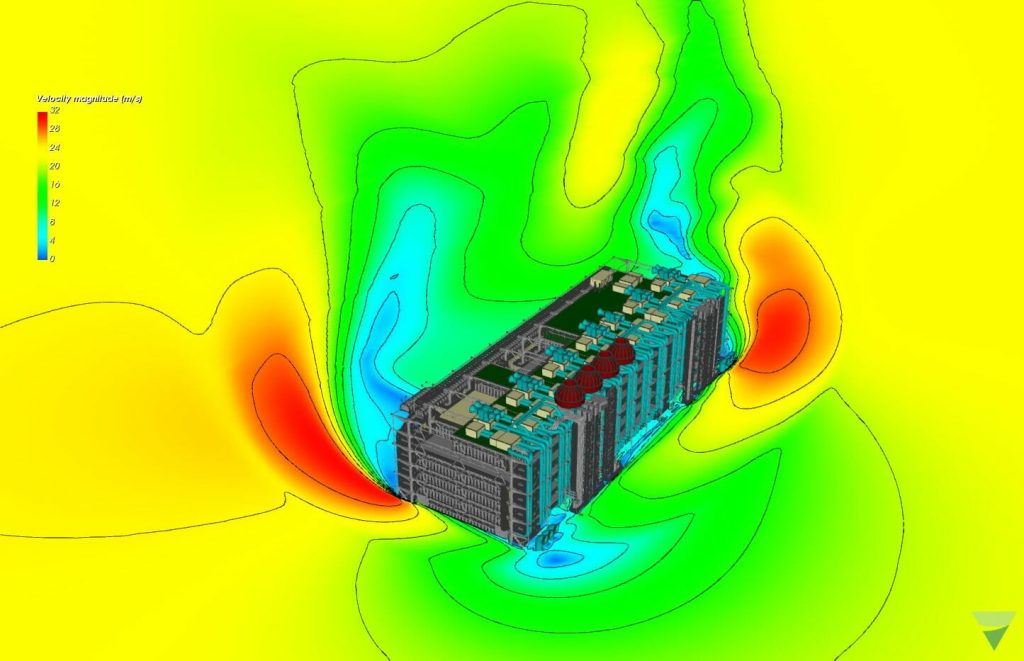
Wind loading in Singapore requires special consideration due to the tropical climate and occasional severe weather events. While Singapore is not in a typhoon belt, wind speeds during thunderstorms can be significant, particularly affecting tall buildings. The basic wind speed for Singapore is specified as 33.5 m/s (3-second gust speed at 10m height), with appropriate factors for height, terrain, and building characteristics. Wind tunnel testing is often required for buildings exceeding 200m in height or those with unusual shapes that may experience complex wind effects.
The selection of an appropriate structural system is crucial for high-rise building design, influencing not only structural performance but also construction cost, speed, and architectural flexibility. In Singapore, various structural systems are employed depending on building height, usage, and architectural requirements. For buildings up to 40 stories, reinforced concrete shear wall systems or frame-shear wall dual systems are commonly used, providing adequate lateral stiffness while maintaining construction economy. These systems utilize reinforced concrete core walls, typically housing elevator and stairwell shafts, working in conjunction with perimeter moment frames to resist lateral loads.
For super high-rise buildings exceeding 40 stories, more sophisticated systems become necessary. Outrigger and belt truss systems are frequently employed, where outrigger arms connect the central core to perimeter columns, effectively mobilizing the axial stiffness of perimeter columns to resist overturning moments. This system has been successfully implemented in several iconic Singapore towers, providing efficient lateral load resistance while minimizing core wall thickness. The optimal location of outriggers requires careful analysis, typically placed at mechanical floors where architectural impact is minimized.
Tube systems, including framed tubes and bundled tubes, represent another category of efficient structural systems for very tall buildings. These systems treat the building perimeter as a hollow cantilever beam, with closely spaced columns and deep spandrel beams creating a rigid tube that efficiently resists lateral loads. The effectiveness of tube action depends on maintaining relatively uniform column spacing and minimizing openings in the tube face, which can be challenging given architectural desires for corner windows and varied facades.
Wind loading represents the primary lateral load for high-rise buildings in Singapore, given the absence of significant seismic activity. Wind effects on tall buildings include both static wind pressures and dynamic effects such as vortex shedding, galloping, and flutter. The assessment of wind loads begins with code-based procedures for buildings of regular shape and moderate height, but wind tunnel testing becomes essential for tall or unusually shaped buildings where wind-structure interaction effects become significant.
Dynamic analysis of high-rise buildings requires consideration of the building’s natural frequencies and mode shapes, particularly the fundamental sway modes that typically govern wind-induced response. Modern computational tools enable complex modal analysis, with hundreds of modes considered to capture higher-mode effects and coupled lateral-torsional behavior. The dynamic amplification factor, representing the ratio of dynamic to static response, must be carefully evaluated, particularly for slender buildings with low natural frequencies that may approach the dominant frequencies of wind turbulence.
The accumulation of vertical loads in high-rise buildings creates significant challenges in column design and load transfer to foundations. Differential shortening between vertical elements, particularly between heavily loaded interior columns and lighter perimeter columns, must be carefully considered in design and construction planning. This differential movement can affect floor levelness, partition integrity, and cladding systems, requiring compensation through construction leveling or connection details that accommodate relative movement.
The structural systems employed in low-rise buildings vary significantly based on functional requirements, span lengths, and loading conditions. Reinforced concrete frame structures remain popular for residential and commercial applications, offering fire resistance, durability, and design flexibility. These structures typically utilize beam-slab systems with columns arranged on regular grids, though architectural requirements often necessitate longer spans and irregular column layouts. Post-tensioned flat slabs have gained popularity for commercial and residential buildings, enabling longer spans and reduced floor depths while maintaining acceptable deflection performance.
Structural steel systems offer advantages for industrial and commercial low-rise buildings, particularly where large column-free spaces are required. Portal frame structures are extensively used for warehouse and industrial facilities, providing economical solutions for spans exceeding 20 meters. These structures efficiently resist lateral loads through frame action, with haunched connections at knee and ridge locations enhancing moment capacity. The use of cold-formed steel sections for secondary elements such as purlins and girts further optimizes material usage while maintaining structural adequacy.
Live load reduction factors, as permitted by codes for multi-story buildings, have limited applicability in low-rise structures. However, careful evaluation of actual loading conditions, particularly in industrial facilities, can identify opportunities for optimization. Storage loads in warehouses require special consideration, with high rack storage systems potentially generating concentrated loads exceeding 100 kN per leg. The design must accommodate various storage configurations while ensuring adequate factors of safety against overloading.
Serviceability criteria often govern the design of low-rise buildings, particularly regarding deflection control and vibration performance. Floor systems must satisfy stringent deflection limits to prevent damage to non-structural elements such as partitions and cladding. The typical deflection limit of span/250 for total load and span/360 for imposed load alone requires careful member sizing and potentially the use of pre-cambering for long-span elements. Vibration control becomes critical for buildings housing sensitive equipment or activities, with natural frequency and acceleration limits specified based on usage requirements.
Durability considerations in Singapore’s tropical climate significantly influence material selection and detailing for low-rise buildings. The high humidity and frequent rainfall necessitate adequate concrete cover, appropriate concrete grade selection, and careful detailing of construction joints and penetrations. For steel structures, corrosion protection through galvanizing or paint systems requires specification based on exposure conditions.
Concrete specification in Singapore requires careful consideration of strength requirements, durability criteria, and workability for placement in congested reinforcement. Normal weight concrete with characteristic strengths ranging from C30 to C80 is commonly used, with higher grades employed for high-rise building columns and transfer structures. The selection of concrete grade must balance structural requirements with constructability, as very high strength concrete requires specialized production and quality control measures. The modulus of elasticity and creep coefficients vary with concrete strength and aggregate type, significantly influencing long-term deformations in tall buildings.
Reinforcing steel in Singapore predominantly consists of high yield deformed bars conforming to SS 560, with characteristic yield strength of 500 MPa. The ductility requirements specified in codes ensure adequate rotation capacity for moment redistribution and energy dissipation under extreme loads. Weldable grades are specified where welding is required for splices or attachment of other elements. The use of prefabricated reinforcement cages and high-strength bars up to Grade 600 is increasing, offering productivity improvements and material optimization for heavily reinforced elements.
The design of beams and slabs for flexure follows the rectangular stress block approach for ultimate limit state, with strain compatibility and equilibrium principles governing the analysis. The neutral axis depth limitations ensure ductile behavior, with x/d ratios limited to 0.45 for concrete grades up to C50. This limitation prevents brittle compression failures and ensures adequate warning of impending failure through large deflections and cracking.
Shear design according to SS EN 1992 employs the variable strut inclination method, allowing optimization of shear reinforcement through selection of appropriate strut angles between 21.8° and 45°. The concrete contribution to shear resistance depends on the longitudinal reinforcement ratio, member depth, and concrete strength.
Torsional effects in concrete structures arise from geometric eccentricities, compatibility requirements in continuous structures, and applied torsional loads from cantilever slabs or curved members. The design for torsion employs a space truss analogy with closed stirrups and longitudinal bars resisting torsional moments. Combined effects of shear, torsion, and flexure require careful consideration of reinforcement arrangements to ensure adequate capacity for all load effects while maintaining constructability.
Column design must consider combined axial load and bending moments, with interaction diagrams defining the capacity envelope for various load combinations. The effects of slenderness become significant for columns with effective length to depth ratios exceeding 20, requiring consideration of second-order effects through moment magnification or more refined analysis. In high-rise buildings, column design often involves staged construction analysis to account for sequential loading and time-dependent effects that influence the distribution of axial loads between vertical elements.
Proper reinforcement detailing ensures force transfer between members, prevents brittle failures, and provides robustness against accidental actions. Lap splice lengths must account for bar stress levels, concrete cover, and transverse reinforcement, with staggering of splices to avoid planes of weakness.
Robustness requirements in Singapore mandate provision of tie forces to prevent progressive collapse following localized damage. Peripheral ties, internal ties, and vertical ties must be detailed to carry specified forces, typically related to floor loads and span lengths. The design of transfer structures supporting multiple floors requires enhanced detailing to ensure alternative load paths exist should primary load-bearing elements be damaged.
Structural steel offers distinct advantages for certain building types in Singapore, particularly where speed of construction, long spans, or architectural expression drive the structural solution. The design of steel structures according to SS EN 1993 considers various failure modes including member buckling, lateral-torsional buckling, and connection capacity.
Structural steel grades commonly used in Singapore include S275 and S355 conforming to SS EN 10025, with yield strengths of 275 MPa and 355 MPa respectively. Higher strength steels such as S460 find application in heavily loaded columns and long-span trusses where material optimization provides economic benefits. The selection of steel grade must consider not only strength requirements but also weldability, toughness, and availability.
The design of steel members must address various buckling modes that can precipitate failure at loads well below material yield strength. Compression members require evaluation of flexural buckling about both axes, with effective lengths determined based on end restraint conditions and frame stability. The buckling resistance depends on member slenderness, with reduction factors applied to account for imperfections and residual stresses. For built-up members, additional considerations include shear deformation effects and requirements for intermediate battens or lacings to ensure composite action.
Lateral-torsional buckling represents a critical consideration for beams without continuous lateral restraint. The buckling resistance depends on the unbraced length, section properties, and moment distribution along the member. Design codes provide simplified approaches for standard cases, with more refined analysis required for complex loading or support conditions. The provision of intermediate lateral restraints at appropriate intervals can significantly enhance capacity, though the restraints must possess adequate strength and stiffness to be effective.
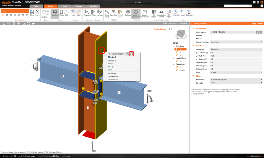
Connection design often represents the most critical aspect of steel structures, with inadequate connections responsible for numerous historical failures. Connections must transfer forces between members while accommodating tolerances, erection requirements, and potential movement during service. The classification of connections as simple, semi-rigid, or rigid significantly influences frame analysis and member design. Simple connections, assumed to transfer shear only, must possess sufficient rotation capacity to accommodate end rotations without developing significant moments. Moment connections must transfer the full member moment capacity while maintaining adequate stiffness to justify rigid connection assumptions in analysis.
Bolted connections using high-strength friction grip (HSFG) bolts provide reliable performance for both shop and site connections. The design must consider bolt shear, bearing on connected parts, and block shear failures. For slip-critical connections, the faying surfaces require appropriate preparation to achieve specified slip coefficients. Preloading of HSFG bolts to specified levels ensures slip resistance under service loads, with direct tension indicators or torque-controlled methods used for installation verification. The edge distances, spacing, and connection geometry must satisfy code requirements while facilitating installation and inspection.
Welding provides efficient connections for steel structures, particularly for moment connections and built-up members. The design of welded connections must consider weld type (fillet or butt), throat thickness, and effective length. Fillet welds, easier to execute and inspect, are preferred for most applications, with full penetration butt welds reserved for highly stressed connections. The welding procedure specifications (WPS) must be qualified through procedure tests, with welders certified for specific positions and materials. Quality control through visual inspection and non-destructive testing ensures weld integrity, particularly for critical connections.
| Connection Type | Typical Application | Advantages | Limitations |
|---|---|---|---|
| Fin Plate | Simple beam connections | Easy erection, tolerant to fit-up | Limited shear capacity |
| End Plate | Moment connections | Shop fabrication, adjustable | Thick plates for large moments |
| Welded Moment | Rigid frame connections | Full moment capacity | Site welding challenges |
| Bolted Splice | Column/beam continuity | Demountable, inspection access | Multiple plates required |
| Base Plate | Column foundations | Load distribution, adjustment | Grouting critical |
Composite construction, combining structural steel with concrete, offers significant advantages for building structures in Singapore. Steel beams acting compositely with concrete slabs achieve greater stiffness and strength than either material alone, enabling longer spans and reduced structural depths. The composite action relies on shear connectors, typically headed studs welded to the steel beam, transferring horizontal shear between steel and concrete. The design must consider both construction stage, where steel beams support wet concrete, and composite stage after concrete hardening.
Composite columns, consisting of steel sections encased in concrete or concrete-filled tubes, provide excellent performance for high-rise buildings. These members combine the strength and ductility of steel with the stiffness and fire resistance of concrete. The design accounts for differential stress-strain relationships, confinement effects, and load transfer between materials. Connection details for composite columns require careful consideration to ensure force transfer while accommodating construction tolerances. The use of composite construction in Singapore continues to grow, particularly for commercial buildings where speed of construction and usable floor area are priorities.
Linear elastic analysis remains the workhorse of structural engineering, providing the basis for design of most building structures under service and ultimate loads. This approach assumes material behavior follows Hooke’s law, with stresses proportional to strains, and geometric changes under load are negligible.
The stiffness method, forming the basis of most commercial software, assembles element stiffness matrices into a global system representing the entire structure. Boundary conditions reflecting support restraints modify the system, with solution providing nodal displacements and member forces.
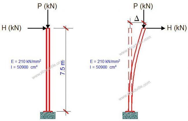
Second-order effects become significant when structural deformations influence the distribution of internal forces, particularly in slender structures subjected to combined axial load and bending. P-Delta effects, arising from vertical loads acting through lateral displacements, amplify moments and deflections in frames and must be considered for structures where second-order effects exceed 10% of first-order values. The analysis can employ iterative approaches, updating geometry based on computed displacements, or direct methods incorporating geometric imperfections.