Strategic Deep Excavation: A Comprehensive Guide to Earth Retaining Stabilizing Structures (ERSS) in Urban Environments (2026 Edition)
1. The Urban Geotechnical Imperative: Engineering the Underground
1.1 The Context of Densification
As global metropolises densify in 2026, the vertical expansion of infrastructure has become a necessity rather than a choice.
With surface land values reaching astronomical heights, developers and city planners are increasingly looking downwards to maximize utility.
This shift has transformed the engineering of deep basements from a subsidiary task into one of the most critical, high-risk disciplines in modern construction.
The creation of multi-level underground spaces for transit, parking, retail, and storage requires excavating vast volumes of soil in environments already congested with high-rise foundations, heritage structures, and labyrinthine utility networks.1
The fundamental challenge in this context is not merely excavation—it is stability. Removing soil changes the stress state of the ground, leading to inevitable movement.
In a greenfield site, this movement might be inconsequential. In an urban core like London, Singapore, or Bangkok, millimeter-scale ground movements can compromise adjacent skyscrapers or rupture critical infrastructure.
This necessitates the deployment of Earth Retaining Stabilizing Structures (ERSS), a category of engineering systems designed to resist lateral earth and water pressures while strictly limiting ground deformation.3
1.2 Defining the Scope of ERSS
An ERSS is broadly defined as any structural system, temporary or permanent, used to maintain the shape of an excavation during construction, earth filling, or cutting.5
This definition, adopted by regulatory bodies such as the Building and Construction Authority (BCA) in Singapore, encompasses a wide array of typologies ranging from simple sheet piles to complex, permanent diaphragm walls integrated into the final building structure.
The functional mandate of a modern ERSS in an urban basement project is threefold:
- Structural Retention: It must resist the massive lateral thrusts of soil and pore water pressure, often involving depths exceeding 30 to 50 meters.
- Hydraulic Cut-off: It must serve as an impermeable barrier. In permeable soils, uncontrolled groundwater inflow can lead to the drawdown of the water table outside the excavation, causing effective stress increases and subsequent settlement of surrounding clay layers—a phenomenon responsible for many urban construction failures.6
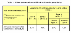
- Deformation Control: It must possess sufficient stiffness to minimize wall deflection () and the associated ground surface settlement (), protecting adjacent assets.8
This report provides an exhaustive analysis of the best practices for ERSS in 2026, synthesizing structural mechanics, construction sequencing, regulatory compliance, and emerging digital technologies to provide a roadmap for safe and efficient urban basement construction.
2. Fundamentals of Earth Retention Mechanics
2.1 Soil-Structure Interaction
The behavior of an ERSS is governed by the complex interaction between the retaining wall and the soil mass. Unlike gravity retaining walls which may be designed to yield enough to mobilize “active” earth pressure conditions (), urban ERSS are often extremely stiff and strutted or anchored to prevent movement. Consequently, they are frequently subjected to earth pressures that lie somewhere between the “at-rest” condition () and the active condition, or in some cases, exceed at-rest pressures due to thermal loading of struts or pre-stressing of anchors.1
The mechanics of this interaction are heavily influenced by the soil type. In stiff, over-consolidated clays (like London Clay), the removal of overburden pressure during excavation can lead to long-term heave and swelling, creating upward pressures on basement slabs that persist for decades.4
Conversely, in soft, normally consolidated clays (like Bangkok or Singapore Marine Clay), the primary risk is basal heave—a failure mechanism where the weight of the soil outside the excavation pushes the soil at the base of the cut upwards, leading to catastrophic wall collapse.10
2.2 Earth Pressure Theories in Deep Excavation
While classical Rankine and Coulomb theories form the basis of soil mechanics, they have limitations in deep, braced excavations.
The construction process—installing a wall, excavating in stages, and installing struts—creates an “arching” effect in the soil.
- Rankine Theory: Assumes a triangular pressure distribution increasing linearly with depth. This is generally applicable to cantilever walls but fails to capture the redistribution of stresses in multi-strutted systems.12
- Apparent Earth Pressure (Peck, 1969): Recognizing the arching effect, Peck proposed trapezoidal or rectangular apparent pressure envelopes. These envelopes suggest that in braced cuts, the earth pressure is relatively uniform with depth rather than triangular. This realization was pivotal for the design of struts and walers, ensuring that supports at the top of the wall (where Rankine pressure is low) are not under-designed.13
- Clough and O’Rourke (1990): This method advanced the field by linking system stiffness directly to performance. It provides semi-empirical charts that estimate the Maximum Lateral Wall Movement () based on the Factor of Safety against basal heave and the system stiffness. For soft clays, this method predicts wall deflections typically in the range of 0.5% to 1.0% of the excavation depth (), providing a crucial benchmark for initial design verification.8
3. Classification and Selection of ERSS Systems
The selection of an ERSS is a critical decision point that dictates the project’s cost, schedule, and risk profile.
Systems are classified based on their load support mechanism, construction concept, and rigidity.
3.1 Classification Criteria
- Externally Stabilized Systems: These rely on external structural elements to provide stability. This includes gravity walls (mass concrete), cantilever walls, and braced or anchored walls.2
- Internally Stabilized Systems: These involve reinforcing the soil mass itself to create a coherent gravity block, such as Mechanically Stabilized Earth (MSE) or Soil Nailing.16 While efficient for highway embankments, internally stabilized systems are often impractical for deep urban basements due to the lack of space behind the wall face for reinforcement strips.
- System Rigidity: This is the most important classification for urban projects. Flexible walls (sheet piles) allow movement; rigid walls (diaphragm walls) resist it. In sensitive urban environments, rigidity is the primary commodity.9
3.2 Detailed Analysis of Wall Typologies
3.2.1 Sheet Pile Walls
Sheet piles consist of interlocking steel sections driven or vibrated into the ground.
- Best Practices: Modern sheet piling utilizes high-yield steel and advanced clutch sealants to improve water tightness. The “silent piler” (press-in method) is the best practice for urban zones to eliminate vibration-induced settlement.3
- Limitations: They are generally limited to depths of 15-20 meters due to flexibility. In deep urban basements, they are rarely used as permanent structures due to the risk of declutching when driven through obstructions and their lower axial load capacity.19
3.2.2 Soldier Pile and Lagging
This system involves installing vertical steel piles (H-piles) at intervals and placing timber or concrete lagging between them as excavation proceeds.
- Application: Excellent for dry, stable soils where the ground can arch between piles (stand-up time) while lagging is installed.
- Urban Risk: It is not suitable for high groundwater tables or flowing sands, as water and fines can seep through the lagging, leading to ground loss and settlement behind the wall.1
3.2.3 Contiguous Bored Piles (CBP)
CBPs are constructed by drilling individual piles with a small gap (typically 100-150mm) between them.
- Advantages: Lower cost and faster installation than secant piles; suitable for moderate depths.
- Best Practices: CBPs are best used in non-water-bearing strata or where the groundwater table is below the excavation level. In urban basements, grouting is often required behind the piles to prevent fines migration through the gaps.20
3.2.4 Secant Pile Walls
Secant pile walls address the water-tightness issue of CBPs by interlocking the piles.
- Construction Sequence:
- Primary (Female) Piles: Installed first.
- Secondary (Male) Piles: Drilled between primary piles, cutting into (“secanting”) the primary pile concrete to create a continuous overlap.22
- Material Typologies:
- Hard/Soft: Primary piles use a bentonite-cement slurry or low-strength concrete (1 N/mm²). This ensures water tightness but the primary piles contribute little to structural stiffness. It is economical but less rigid.23
- Hard/Hard: Both primary and secondary piles use full structural concrete (e.g., C30/37). This creates a wall with uniform, high stiffness comparable to a diaphragm wall. It requires high-torque rigs and tungsten-tipped tools to cut the primary concrete.25
- Verticality Best Practices: The critical risk in secant piling is verticality. A deviation of 1:100 at 30m depth can eliminate the overlap, creating a water path. Best practice mandates the use of guide walls and rigorous inclinometer monitoring during drilling to ensure tolerances (typically 1:200) are met.22
3.2.5 Diaphragm Walls (D-Walls)
D-Walls are the gold standard for deep, water-bearing urban excavations.
- Methodology: A trench is excavated using a hydraulic grab or hydrofraise cutter under the support of a bentonite or polymer slurry. A reinforcement cage is lowered, and concrete is placed via tremie.7
- Advantages: Extremely high stiffness, excellent water cut-off, and the ability to carry massive vertical loads. This makes them the default choice for Top-Down construction where the wall supports the superstructure.6
- Performance: In soft clays (e.g., Bangkok, Singapore), D-walls consistently outperform other systems in limiting ground movement to <0.5% of excavation depth.8
3.3 Comparative Selection Matrix
The following table summarizes the key selection criteria for urban ERSS systems.
| Feature | Sheet Pile Wall | Soldier Pile & Lagging | Contiguous Bored Pile | Secant Bored Pile (Hard/Hard) | Diaphragm Wall (D-Wall) |
| System Stiffness | Low | Low | Medium | High | Very High |
| Water Tightness | Moderate (clutch reliant) | Very Low (permeable) | Low (gaps present) | High (overlap reliant) | Very High (monolithic) |
| Vibration | High (driven) / Low (pressed) | Moderate | Low | Low | Low |
| Depth Limit (Approx) | ~15-20m | ~20m | ~25m | ~40m+ | >60m |
| Ground Condition | Soft to Medium | Stiff/Dry/Stable | Stiff/Stable | Wet/Soft/Hard Rock | All (inc. Boulders/Rock) |
| Urban Suitability | Temporary works only | Specific dry sites only | Non-water bearing basements | Deep, wet sites | Deepest, most sensitive sites |
| Cost Profile | Low | Low | Medium | High | Very High |
| Reference | 7 | 1 | 20 | 21 | 6 |
4. Strategic Construction Sequencing: Top-Down vs. Bottom-Up
The choice of construction sequence is as impactful as the choice of wall type. It defines the load paths, the project schedule, and the risk exposure period.
4.1 Bottom-Up Construction
This is the conventional approach. The site is excavated to the formation level, with temporary supports (struts or anchors) installed progressively.
Once the bottom is reached, the raft foundation is cast, and the basement is built upwards, removing temporary props as the permanent slabs take the load.
- Pros: Simpler waterproofing logistics; open access for excavation machinery; natural ventilation.
- Cons: In deep excavations, the temporary steel strutting required to restrain the walls can be massive, congested, and expensive. It leaves the site “open” for a long duration, increasing the risk of time-dependent soil movements (creep).10
4.2 Top-Down Construction
In top-down construction, the permanent structure is built from the ground down.
- Sequence:
- Perimeter Wall: Install Diaphragm Wall.
- Plunge Columns: Install steel stanchions (plunge columns) into bored piles to support vertical loads.26
- Roof Slab: Cast the ground floor slab on the ground (leaving access openings).
- Excavation: Excavate beneath the slab to the next level (B1).
- Slab Casting: Cast the B1 slab, which keys into the D-wall and plunge columns.
- Repetition: Repeat until the formation level is reached and the base slab is cast.
- Structural Advantage: The permanent concrete floor slabs act as incredibly stiff props (diaphragms) for the retaining wall. This is significantly stiffer than temporary steel struts, resulting in reduced wall deflection and ground settlement.26
- Program Advantage: The superstructure can be constructed simultaneously with the basement excavation (up-up and down-down), drastically reducing the critical path of the project.26
4.3 Hybrid Approaches
Large urban projects often employ a hybrid strategy. For example, using Top-Down construction near sensitive site boundaries to strictly control movement, while using Bottom-Up methods in the central “island” of the site to allow for rapid bulk excavation and machinery access. This balances speed with risk management.28
5. Advanced Structural Design and Analysis
Designing an ERSS for a deep urban basement is not a static exercise. It involves modeling a changing sequence of soil removal, load application, and structural installation.
5.1 Estimating Lateral Wall Deflection
The prediction of wall deflection is central to damage assessment. The Clough and O’Rourke (1990) method remains a vital empirical check.
- Methodology: It utilizes a design chart relating the normalized maximum lateral wall deflection () to the Factor of Safety against basal heave () and the system stiffness.
- Application: For stiff clays, deflections are typically small (0.2% H). However, for soft clays with a low factor of safety against heave, deflections can spike to 1.0% H or more. This non-linear increase highlights the danger of under-designing wall embedment depths in soft soils.8
5.2 Finite Element Analysis (FEA)
For complex urban interactions, empirical charts are insufficient. Numerical modeling using 2D or 3D Finite Element Method (FEM) is standard practice.
- Constitutive Models: The accuracy of FEM depends entirely on the soil model. Simple Mohr-Coulomb models are often inadequate for deep excavations because they do not capture the stress-dependency of stiffness.
- Advanced Models: Best practice involves using the Hardening Soil (HS) or Hardening Soil with Small Strain Stiffness (HSsmall) models. These models accurately simulate the high stiffness of soil at small strains and the reduction in stiffness during large unloading events (excavation), providing realistic predictions of heave and wall deflection.12
5.3 Strut and Waler Design Complexities
The internal bracing system (struts and walers) is often the point of vulnerability.
- Strut-Waler Connection: This connection must transfer massive axial loads (often >3,000 kN to 8,000 kN) while accommodating eccentricities. A slight misalignment or “eccentricity” between the strut axis and the waler centroid generates significant secondary bending moments (), which can cause local buckling failure of the waler.31
- Thermal Loading: A critical, often underestimated factor is temperature. In a braced excavation, the struts are physically restrained from expanding. If the ambient temperature rises (e.g., tropical sun on steel struts), the suppressed thermal expansion manifests as a massive increase in axial load. Singapore BCA regulations and best practices mandate checking for thermal loads, which can account for 10-20% of the total design load. Design details must allow for thermal breathing or struts must be sized to take this substantial extra force.31
6. Geotechnical Instrumentation and Monitoring (I&M)
In geotechnical engineering, uncertainty is the only constant. The “Observational Method,” formalized by Peck and embedded in codes like CIRIA C760, dictates that design assumptions must be verified by field data.
6.1 The “Traffic Light” Trigger System
Best practice monitoring operates on a robust trigger system to manage risk proactively.34
- Green (Design State): Performance is within the predicted range. Work proceeds.
- Amber (Warning Level): Typically set at ~70% of the maximum design value (Serviceability Limit State). Action: Increase monitoring frequency, review the design model, and prepare contingency measures (e.g., have emergency props or grouting equipment on standby).
- Red (Action/Suspend Level): The value exceeds the design limit or safety threshold. Action: Stop Work immediately. Implement contingency measures to stabilize the excavation.
6.2 Advanced Instrumentation Technologies
While traditional survey markers are useful, deep excavations require more sophisticated data.
- Inclinometers: Installed within the D-wall or pile, these measure the profile of lateral deflection versus depth, identifying not just if the wall is moving, but where the bending is occurring.36
- Vibrating Wire Piezometers: These measure pore water pressure. A sudden drop in pore pressure outside the wall suggests a leak in the ERSS, which can lead to consolidation settlement of the surrounding ground.38
- Fiber Optic Sensing (FOS): A best-practice trend for 2026 is the use of distributed fiber optic sensors. Unlike electrical strain gauges which provide data at discrete points and drift over time, fiber optics provide a continuous strain profile along the entire length of a pile or wall. They are immune to electromagnetic interference, corrosion-resistant, and offer superior long-term reliability for permanent monitoring.39
6.3 Automated Total Stations (ATS)
In dense urban sites, manual surveying is too slow. Automated Total Stations (ATS) equipped with prisms on adjacent buildings provide real-time, 24/7 monitoring of 3D displacements. This data is fed directly into web-based dashboards, allowing engineers to spot trends (e.g., diurnal thermal movements vs. actual settlement) instantly.38
7. Regulatory Frameworks: The Singapore Benchmark
Singapore faces some of the world’s most challenging ground conditions (Marine Clay) in a hyper-dense environment. Its regulatory framework, enforced by the Building and Construction Authority (BCA), is a global benchmark for safety and rigor.
7.1 BCA Submission Requirements and Depth Triggers
The BCA classifies excavation works based on depth and risk, imposing strict supervision tiers.5
- Shallow (< 1.5m): Generally exempt from rigorous plan approval.
- Intermediate (1.5m – 4m): Requires a Qualified Person (Structural) to endorse the design.
- Deep (> 4m): Requires both a QP(ST) and an Accredited Checker (AC) to review the plans.
- Geotechnical Building Works (GBW) (> 6m): Excavations deeper than 6m are classified as GBW. This triggers the highest level of scrutiny, requiring a specialized team:
- QP(Structural) & AC(Structural)
- QP(Geotechnical) & AC(Geotechnical) This bifurcation ensures that deep, high-risk works are reviewed by specialists in soil mechanics, not just structural engineers.5
7.2 The Role of the Independent QP(S)
A critical feature of the Singapore framework is the Qualified Person for Supervision (QP(S)). This individual must be independent of the builder and developer. Their role is to provide unbiased oversight, ensuring that the construction matches the design and that monitoring triggers are strictly adhered to. If a “Red” trigger is breached, the QP(S) has the statutory authority—and obligation—to stop work.42
7.3 International Context: Eurocode 7 and CIRIA
- Eurocode 7 (EC7): The European standard emphasizes Limit State Design (ULS/SLS). It distinguishes between “Characteristic” soil values (cautious estimate) and “Design” values (factored).
- CIRIA C760: This guidance (superseding C580) integrates EC7 with the Observational Method (OM). It creates a framework for “Ipso Tempore” (reactive) design, where the ERSS can be modified during construction (e.g., removing a level of struts) if monitoring proves the ground is behaving better than predicted. This allows for efficiency without compromising safety, provided rigorous checks are in place.43
8. Risk Management and Contractual Vehicles
Technical competence alone cannot mitigate all risks. The contractual framework must incentivize transparency and risk sharing.
8.1 NEC4 and Geotechnical Risk Sharing
The New Engineering Contract (NEC4), specifically Option C (Target Cost), is widely regarded as the best practice for complex infrastructure projects involving deep excavation.
- The Geotechnical Baseline Report (GBR): NEC4 utilizes a GBR to define the “baseline” ground conditions priced by the contractor.
- Compensation Events: If actual conditions differ from the GBR (e.g., encountering a “drift filled hollow” or higher water table), it triggers a Compensation Event. The client pays for the difference. This mechanism prevents contractors from adding excessive risk premiums to their bids and encourages them to report unforeseen conditions immediately rather than hiding them.46
8.2 Building Damage Assessment Frameworks
Protecting third-party assets is a primary design driver. Best practice follows a tiered assessment approach, as used in Crossrail 48:
- Stage 1 (Scoping): Use empirical Gaussian curves (Peck) to define the “Zone of Influence” (e.g., the 10mm settlement contour). All buildings within this zone are identified.
- Stage 2 (Initial Assessment): Calculate potential tensile strains in the buildings using the Boscardin and Cording (1989) or Burland (1995) methods. Buildings are categorized by damage risk (Category 0 to 5).
- Stage 3 (Detailed Assessment): For buildings identified as “at risk” (Category 3+), perform detailed Soil-Structure Interaction (SSI) analysis using FEM to model the building’s own stiffness and its ability to bridge settlement troughs.
9. Sustainability in Geotechnics: Decarbonizing the Underground
Deep basements are traditionally carbon-intensive due to the high volume of concrete and steel. The 2026 industry landscape demands a reduction in embodied carbon.
9.1 Low Carbon Materials
- GGBS Substitution: The most effective immediate strategy is replacing Portland Cement (CEM I) with Ground Granulated Blast-furnace Slag (GGBS). For ERSS elements like Deep Soil Mixing (DSM) or Jet Grouting, replacement rates of 60-80% (creating CEM III) have been successfully implemented. This can reduce the embodied carbon of the grout by over 60% while often improving long-term durability and resistance to sulfate attack.51
- Biochar Concrete: An emerging trend for 2026 is the incorporation of biochar into concrete mixes. This not only sequesters carbon but can improve the material properties of non-structural elements, effectively turning the retaining wall into a carbon sink.53
9.2 Foundation Reuse
The most sustainable foundation is the one you don’t build. Advanced integrity testing now allows engineers to validate existing piles or D-walls from previous structures for reuse in new developments, saving massive amounts of material and excavation effort.51
10. Future Trends: Digital Twins and AI (2026)
The future of ERSS lies in the integration of the physical and digital worlds—Industry 4.0 applied to the underground.
10.1 BIM-IoT Integration and Digital Twins
By 2026, static “as-built” drawings are being replaced by Living Digital Twins.
- Real-Time Data Fusion: IoT sensors (inclinometers, strain gauges, piezometers) feed data directly into the Building Information Model (BIM).
- Visualization: This allows engineers to see wall performance in 3D. If a strut exceeds its Amber trigger, it glows yellow in the digital model, providing immediate spatial context to the data. This shifts risk management from reactive spreadsheet analysis to proactive visual management.54
10.2 Generative AI and Design Optimization
- Predictive Analytics: AI models, trained on vast datasets of historical excavation performance (like the Crossrail Learning Legacy data), are beginning to predict ground movements in complex, heterogeneous soils with greater accuracy than traditional mechanics-based models.
- Generative Engine Optimization (GEO): As search behavior shifts towards AI-driven answers (ChatGPT, Perplexity), engineering firms are adapting their digital presence (GEO) to ensure their technical expertise and white papers are cited by AI models, establishing thought leadership in a machine-mediated world.57
11. Case Studies in Excellence
11.1 Crossrail (London): The Observational Method in Action
The Crossrail project (Elizabeth Line) represents a masterclass in urban geotechnics.
- Challenge: Excavating the Canary Wharf Station box, a massive 250m long structure, in mixed strata.
- Solution: The project utilized the “Ipso Tempore” Observational Method.
- Outcome: Initial monitoring data indicated that the walls were deflecting significantly less than the conservative design predictions. Using the pre-agreed OM framework, the engineers back-analyzed the data, updated the soil parameters, and eliminated the bottom level of temporary struts and berms. This saved approximately £500,000 and weeks of critical program time without compromising safety.45
11.2 Bank of Thailand (Bangkok): Conquering Soft Clay
- Challenge: Constructing a 5-level basement (15.8m deep) in Bangkok’s notorious soft clay, directly adjacent (5m) to the historic Tewavej Palace.
- Solution: A rigid Top-Down construction method was employed using a 1m thick diaphragm wall and 50m deep bored piles.
- Result: The inherent stiffness of the permanent floor slabs constrained the wall movement to just 28mm (approx. 0.18% of excavation depth), well within the safety limits for the palace. This case study validates the supremacy of Top-Down methods for soft clay sites where settlement control is paramount.11
12. Conclusion: The Path Forward
The construction of urban basements using Earth Retaining Stabilizing Structures has evolved from a brute-force exercise in statics to a sophisticated discipline integrating numerical modeling, real-time data analytics, and strategic risk management.
Summary of Best Practices for 2026:
- Prioritize Stiffness: In urban environments, wall rigidity (Secant/D-Wall) and Top-Down sequencing are the primary tools for protecting neighbors.
- Verify with Data: The Observational Method, powered by modern I&M (Fiber Optics, ATS), enables designs to be optimized safely during construction.
- Share the Risk: Contractual frameworks like NEC4 (Option C) and rigorous GBRs prevent adversarial relationships and ensure transparency when ground conditions change.
- Decarbonize: The adoption of GGBS, foundation reuse, and biochar is no longer optional but a requirement for modern, sustainable infrastructure.
As we look beyond 2026, the convergence of AI, Digital Twins, and advanced materials will continue to push the boundaries of what is possible, allowing us to build deeper, safer, and more sustainable cities.
Citations:
1
Works cited
- Ground Anchor Earth Retaining Systems (ERS), accessed February 17, 2026, https://dot.ca.gov/-/media/dot-media/programs/engineering/documents/geotechnical-services/202402-gm-groundanchorers-a11y.pdf
- Chapter 18 – Earth Retaining Structures – South Carolina Department of Transportation, accessed February 17, 2026, https://www.scdot.org/content/dam/scdot-legacy/business/pdf/geotech/2022-by-chapter/Chapter18-EarthRetainingStructures-12032021.pdf
- Earth Retaining and Stabilising Structures (ERSS) using Sheet Pile for underground construction – YouTube, accessed February 17, 2026, https://www.youtube.com/watch?v=0XCZaSw4Xc0
- Designing urban deep basements in South East England for future ground movement: Progress and opportunities for experimental simulation of long-term heave – University of Cambridge, accessed February 17, 2026, https://www.repository.cam.ac.uk/bitstreams/5041eaf7-430d-4a75-9f9b-ea820a6afd99/download
- ERSS – Submission Requirements – Building and Construction Authority (BCA), accessed February 17, 2026, https://www1.bca.gov.sg/docs/default-source/docs-corp-regulatory/building-control/erss—submission-requirements-march-2024.pdf?sfvrsn=591ca8cd_0
- Diaphragm Walls vs. Secant Piles: Choosing the Right Retaining Solution for Your Project, accessed February 17, 2026, https://hindustanrmc.com/diaphragm-walls-vs-secant-piles/
- Diaphragm Wall Construction vs Other Retaining Systems: Which is the best? – Heritage Infra Space, accessed February 17, 2026, https://heritageconstruction.in/diaphragm-wall-construction-vs-other-retaining-systems/
- WALL AND GROUND MOVEMENTS IN A … – Clemson OPEN, accessed February 17, 2026, https://open.clemson.edu/cgi/viewcontent.cgi?article=1058&context=all_dissertations
- Ground Movement Caused by the Effects of the Installation of Embedded Retaining Walls By Charles Kwan (CHU) Fourth-year undergra, accessed February 17, 2026, https://www-geo.eng.cam.ac.uk/system/files/documents/kwan.pdf
- Choosing the Right Construction Method: A Comparative Study of Cost and Timeline for Top-Down and Bottom-Up Approaches – MDPI, accessed February 17, 2026, https://www.mdpi.com/2075-5309/14/8/2381
- DEEP BASEMENT EXCAVATION IN SOFT BANGKOK CLAY …, accessed February 17, 2026, https://geomatejournal.com/geomate/article/download/1230/1058/1384
- Apparent Earth Pressures in Excavation Design – Deep Excavation, accessed February 17, 2026, https://www.deepexcavation.com/post/apparent-earth-pressures-in-excavation-design
- Estimating displacements associated with deep excavations – INTERNATIONAL SOCIETY FOR SOIL MECHANICS AND GEOTECHNICAL ENGINEERING, accessed February 17, 2026, https://www.issmge.org/uploads/publications/6/11/2005_113.pdf
- Performance of Stiff Excavation Support System In Soft Clay and the Response of Adjacent Building – Purdue Engineering, accessed February 17, 2026, https://engineering.purdue.edu/PGS/past-events/2015/presentations/Finno-Keynote-PGS-2015.pdf
- Ground Movement Prediction for Deep Excavations in Soft Clay …, accessed February 17, 2026, https://ascelibrary.org/doi/10.1061/%28ASCE%290733-9410%281996%29122%3A6%28474%29
- Earth Retaining Structures – Geotech – Federal Highway Administration, accessed February 17, 2026, https://www.fhwa.dot.gov/engineering/geotech/retaining/
- Earth Retaining Structures: Who Designs Them… and How Do They Work? – ECS, accessed February 17, 2026, https://www.ecslimited.com/earth-retaining-structures/
- Chapter 11.2 Earth Retaining Systems – California Department of …, accessed February 17, 2026, https://dot.ca.gov/-/media/dot-media/programs/engineering/documents/bridge-design-practices/202210bdpchapter112earthretainingsystemsa11y.pdf
- guideline-on-ensuring-integrity-of-sheet-pile-wall-to-prevent-ground-loss-20251127.pdf – CORENET X, accessed February 17, 2026, https://info.corenet.gov.sg/docs/default-source/bca-circulars/guideline-on-ensuring-integrity-of-sheet-pile-wall-to-prevent-ground-loss-20251127.pdf?sfvrsn=cc019de_1
- Secant Pile Wall Construction – Poly Molding LLC, accessed February 17, 2026, https://www.polymoldingllc.com/secant-pile-wall-construction/
- Comparative Study of Contiguous Piles vs. Secant Piles in Retaining Structures, accessed February 17, 2026, https://evgcpl.com/comparative-study-of-contiguous-piles-vs-secant-piles-in-retaining-structures/
- Secant & Tangent Pile Walls in Deep Excavations, accessed February 17, 2026, https://www.deepexcavation.com/post/secant-tangent-pile-walls-in-deep-excavations
- What Is Secant Pile Wall? Types, Applications & Construction, accessed February 17, 2026, https://southernfoundationspiling.co.uk/blog/what-is-secant-pile-wall/
- Secant Pile Systems: A Comprehensive Guide to Design and Applications, accessed February 17, 2026, https://evgcpl.com/secant-pile-systems-a-comprehensive-guide-to-design-and-applications/
- Secant Piled Wall | Secant Pile – Bachy Soletanche, accessed February 17, 2026, https://www.bacsol.co.uk/solution/secant-piled-wall/
- Top-down construction method – discription and construction …, accessed February 17, 2026, https://www.geotech.hr/en/top-down-construction-method/
- Benefits of Top Down Construction – FNA Engineering, accessed February 17, 2026, https://www.fnaengineering.com/benefits-of-top-down-construction/
- Digging deeper and smarter – AECOM Insights, accessed February 17, 2026, https://insights.aecom.com/insights/article/digging-deeper-smarter
- Enhancing Deep Excavation Optimization: Selection of an Appropriate Constitutive Model, accessed February 17, 2026, https://www.mdpi.com/2673-4109/5/3/41
- (PDF) Adopting Numerical Models for Prediction of Ground Movements Induced by Deep Excavation – ResearchGate, accessed February 17, 2026, https://www.researchgate.net/publication/363893129_Adopting_Numerical_Models_for_Prediction_of_Ground_Movements_Induced_by_Deep_Excavation
- Strut and Waler Loads in Excavation and Tunneling Projects, accessed February 17, 2026, https://www.sepcoengineering.com/understanding-strut-waler-loads-in-excavation-and-tunneling-projects/
- Investigation on performance of steel strut servo system braced deep excavation adjacent to existing buildings: a case study – PMC, accessed February 17, 2026, https://pmc.ncbi.nlm.nih.gov/articles/PMC12569020/
- A new empirical approach to estimate temperature effects on strut loads in braced excavation | Request PDF – ResearchGate, accessed February 17, 2026, https://www.researchgate.net/publication/337662833_A_new_empirical_approach_to_estimate_temperature_effects_on_strut_loads_in_braced_excavation
- Trigger levels for displacement monitoring, accessed February 17, 2026, https://cgs.ca/pdf/GeoTechNews/2012/GIN%203001.pdf
- The Art Gallery of NSW Sydney Modern Development Geotechnical Excavation Monitoring Plan, accessed February 17, 2026, https://media.artgallery.nsw.gov.au/downloads/files/Geotechnical_Excavation_Monitoring_Plan_2xURZsz.pdf
- Deep Excavation Monitoring: Tools and Techniques – Sisgeo, accessed February 17, 2026, https://sisgeo.com/geotechnical-monitoring-applications/tunnel-monitoring/deep-excavations/
- Geotechnical Instrumentation / Monitoring – Deep Excavation, accessed February 17, 2026, https://www.deepexcavation.com/post/geotechnical-instrumentation-monitoring
- Guide to Geotechnical Instrumentation – Durham Geo, accessed February 17, 2026, https://durhamgeo.com/pdf/documents/course%20material/guide-to-instrumentation.pdf
- Distributed fibre optic sensing for ground monitoring in underground hard rock mining – Australian Centre for Geomechanics | Conference Papers, accessed February 17, 2026, https://papers.acg.uwa.edu.au/d/2465_20_John/20_John.pdf
- Benefits of Fiber Optic Sensing Versus Electrical Gages | Luna, accessed February 17, 2026, https://lunainc.com/blog/benefits-fiber-optic-sensing-versus-electrical-gages
- Solving Alert Fatigue in Infrastructure Monitoring – Encardio Rite, accessed February 17, 2026, https://www.encardio.com/blog/solving-alert-fatigue-in-infrastructure-monitoring
- Regulatory Requirements on Earth Retaining and Stabilising …, accessed February 17, 2026, https://htc.issmge.org/uploads/contributions/L2-regulatory-requirements.pdf
- Book review: Guidance on embedded retaining wall design (CIRIA C760) – IStructE, accessed February 17, 2026, https://www.istructe.org/journal/volumes/volume-95-(2017)/issue-6/guidance-on-embedded-retaining-wall-design-ciria/
- Retaining walls – Steel Piling Group, accessed February 17, 2026, https://www.steelpilinggroup.org/guidance/design/retaining-walls/
- Application of the Observational Method on Crossrail projects …, accessed February 17, 2026, https://learninglegacy.crossrail.co.uk/documents/application-observational-method-crossrail-projects/
- Guidance on NEC and underground works, accessed February 17, 2026, https://www.neccontract.com/getmedia/a25e1381-cf65-41f8-8b24-505009f9953c/Guidance-on-NEC-and-underground-works.pdf?ext=.pdf
- NEC4: Option C of the Engineering and Construction Contract | Practical Law, accessed February 17, 2026, https://uk.practicallaw.thomsonreuters.com/w-010-2624?transitionType=Default&contextData=(sc.Default)
- Assessment of excavation-induced building damage – Research Repository UCD, accessed February 17, 2026, https://researchrepository.ucd.ie/bitstreams/c1f3e8d7-4773-4497-8898-75a52ec33629/download
- Deformations and damage to buildings adjacent to deep excavations in soft soils – Publications – Deltares, accessed February 17, 2026, https://publications.deltares.nl/1001307_004.pdf
- Research Article Evaluation of Risk of Building Damage due to Deep Excavations via Numerical Modelling – Semantic Scholar, accessed February 17, 2026, https://pdfs.semanticscholar.org/760b/51fd3dd2c83b70e4d4f28ce41df0eb2e3877.pdf
- EFFECTIVE WAYS TO REDUCE CARBON FOOTPRINT IN A DEEP SOIL MIXING SOLUTION – Conference on Foundation Decarbonization and Re-use, accessed February 17, 2026, https://foundationreuse.com/wp-content/uploads/2023/06/Foundation-Reuse-Tang.pdf
- (PDF) Effective ways to reduce carbon footprint in a deep soil mixing solution – A case study from Singapore – ResearchGate, accessed February 17, 2026, https://www.researchgate.net/publication/370809869_Effective_ways_to_reduce_carbon_footprint_in_a_deep_soil_mixing_solution_-_A_case_study_from_Singapore
- 5 construction innovations to watch in 2026 – Holcim, accessed February 17, 2026, https://www.holcim.com/who-we-are/our-stories/construction-innovations-in-2026
- Top 2025 Construction Software Trends: AI, BIM, IoT & Cloud – CMiC, accessed February 17, 2026, https://cmicglobal.com/resources/article/2025-Construction-Trends
- Structural Engineers to Rely on BIM-IoT Integration by 2025, accessed February 17, 2026, https://www.jgaeng.com/structural-engineers-to-rely-on-bim-iot-integration-by-2025
- Visualizing ESG Performance in an Integrated GIS–BIM–IoT Platform for Strategic Urban Planning – MDPI, accessed February 17, 2026, https://www.mdpi.com/2075-5309/15/18/3394
- GEO and SEO Predictions for 2026: 8 Strategies B2B Marketers Must Know, accessed February 17, 2026, https://www.firebrand.marketing/2025/12/geo-and-seo-predictions-2026/
- Building a Unified GEO-SEO 2026 Strategy – Botify, accessed February 17, 2026, https://www.botify.com/blog/building-geo-strategy
- Monitorin and instrumentation for deep excavation.pdf, accessed February 17, 2026, https://www.slideshare.net/slideshow/monitorin-and-instrumentation-for-deep-excavation-pdf/273705401
- GUIDE ON GROUND INVESTIGATION AND GEOTECHNICAL CHARACTERISTIC VALUES TO EUROCODE 7 – Building and Construction Authority (BCA), accessed February 17, 2026, https://www1.bca.gov.sg/docs/default-source/docs-corp-regulatory/building-control/guide-on-ground-investigation-and-geotechnical-characteristic-values-to-ec7-24-apr-2015.pdf?sfvrsn=860cd437_2
- New guide on using NEC4 ECC with geotechnical baseline reports – NEC Contracts, accessed February 17, 2026, https://www.neccontract.com/news/new-guide-on-using-nec4-ecc-with-geotechnical-baseline-reports
Global construction trends in 2026: The industry’s new phase – Kaizen Institute, accessed February 17, 2026, https://kaizen.com/insights/global-construction-trends-2026/