
Introduction
Rising groundwater, heavy rainfall, soil saturation, and inadequate drainage are common causes of groundwater hydrostatic pressure on permanent basement walls, creating continuous lateral water loads that act for decades. In permanent basement structures, that sustained loading leads to long term creep in both concrete elements and surrounding soft soils; in Singapore’s marine clay geology—where the water table often sits within a metre of ground level and soil permeability can be as low as 10⁻⁹ to 10⁻¹⁰ m/s—this combination can progressively reduce structural stability over a 50–100 year design life if it is not properly allowed for.
This article is written for engineering and architectural consultants, structural engineers, developers, contractors, facility managers, and government agencies responsible for designing, constructing, or managing permanent basement structures in tropical regions, especially Singapore. It focuses on ULS groundwater level modelling, relief drain design assumptions and their actual effectiveness, buoyancy and uplift calculations, concrete and soil creep mechanisms under sustained hydrostatic loading, and practical mitigation measures for long-term durability, with references to Eurocode 7, Singapore’s Building Control Authority (BCA) requirements, and local case conditions rather than temporary excavation support.
Groundwater hydrostatic pressure long term creep in permanent basement walls means sustained groundwater pressure applies a permanent lateral load to the wall system, while groundwater can also force water through existing cracks along the path of least resistance, increasing local deterioration and stress concentration over time. If these effects are ignored, wall deformation, soil movement, cracking, seepage, and long-term serviceability and stability risks become more likely.
After reading this article, you will understand:
-
How to establish ULS groundwater levels using return-period analysis and climate projections
-
How relief drain sizing and partial effectiveness assumptions influence hydrostatic load calculations
-
How to perform buoyancy and uplift checks with appropriate partial factors
-
How concrete and soil creep interact under sustained hydrostatic loading in tropical conditions
-
Practical mitigation strategies for long term durability in Singapore’s challenging soil conditions
Understanding Groundwater Hydrostatic Pressure in Basement Walls
In permanent basement structures, hydrostatic pressure refers to the pressure exerted by standing groundwater acting continuously on foundation walls and base slabs once the structure is in service. This is fundamentally different from transient construction-phase scenarios where dewatering temporarily lowers groundwater levels. After completion, the water table recovers and hydrostatic water pressure becomes quasi-static-groundwater pressure may remain present continuously for months or years, creating sustained mechanical stress on below-grade concrete.
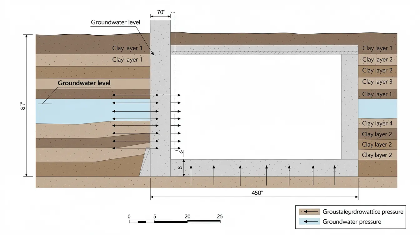
In Singapore, the combination of high groundwater, reclaimed land, and very soft marine clay (Upper Marine Clay with water content of 60–80%, undrained shear strength of 10–30 kPa near surface) means that pore water pressures dissipate extremely slowly. The primary causes hydrostatic pressure in these conditions are the low permeability of saturated soil surrounding the basement and the proximity of the water table to ground level. Hydrostatic pressure increases approximately linearly with water depth-specifically by about 0.43 psi per foot of water depth, meaning ten feet of water can exert over 4 psi on foundation walls. Clay soils increase hydrostatic pressure risks due to low permeability, as water cannot drain away from the wall system efficiently, so trapped groundwater follows the path of least resistance and can force water against cracks or joints when drainage is limited.
Ultimate Limit State Groundwater Levels
ULS groundwater conditions for permanent basement design are defined as the most adverse groundwater levels that a structure must resist without failure, determined using statistical return periods and conservative assumptions. Eurocode 7 (EN 1997-1) specifies that design values of groundwater pressure for ULS must correspond to characteristic upper piezometric pressure (Gwk,sup) or lower (Gwk,inf), whichever produces the worst effect for the limit state being checked. When data is insufficient, cautious estimates must be used.
For tropical regions like Singapore, ULS groundwater modeling must incorporate climate change considerations. Sea level rise projections of 0.5–1.0 m over the next 50–100 years directly modify the upper piezometric levels used in design. Eurocode 7 typically uses a 2% annual probability of exceedance for ULS (approximately a 50-year return period), though 100-year return periods are increasingly adopted for critical infrastructure. Singapore’s Land Transport Authority (LTA) standards apply partial factors of approximately 1.35 for permanent groundwater level vertical water pressure in ULS design, with different factors for accidental groundwater level scenarios.
Proper Drainage and Relief Drain Design Assumptions
Relief drain design assumptions critically affect the calculated hydrostatic pressure distribution on basement walls, and poor drain performance leaves them exposed to lateral loads from water trapped behind the wall. Drainage systems including weep holes, drainage blankets, french drains, and under-slab drains are intended to relieve pressure builds behind the wall by allowing groundwater to flow away from the structure. By interrupting the path of least resistance, drains reduce the tendency for groundwater to accumulate and force water toward the wall system. French drains help divert water away from foundations, while weep holes in retaining walls allow trapped water to escape. Sump pumps automatically remove excess groundwater from basements when water accumulates beyond drain capacity.
However, long term performance of these systems rarely matches initial design assumptions. In practice, only partial drainage effectiveness may be achieved: clogged gravel or geotextile filters, sediment ingress, reduced hydraulic gradients, and lack of maintenance can reduce effectiveness to 30–50% of the fully drained assumption. For ULS design, engineers typically bracket two extreme scenarios-undrained (full hydrostatic load) and drained (full relief)-then adopt a realistic intermediate assumption. For permanent basements, the more adverse (higher pressure) case governs. Singapore’s SS 637:2018 standard mandates that basement waterproofing systems must resist negative-side hydrostatic pressure permanently, acknowledging that drainage cannot be relied upon as the sole protective layer.
Effective groundwater drainage is essential for long-term performance of basement walls, but managing hydrostatic pressure requires designing for the scenario where drains underperform. This sustained pressure is precisely what drives the creep phenomena examined in the next section.
Long-Term Creep Mechanisms in Permanent Basement Structures
When hydrostatic pressure acts as sustained lateral loads over years and decades, rather than as a single static action, both concrete and surrounding soil undergo time-dependent deformation that simple elastic analysis cannot capture. Understanding these creep mechanisms is essential for any structural modelling design and analysis of deep basement projects.
Concrete Creep Under Sustained Hydrostatic Loading
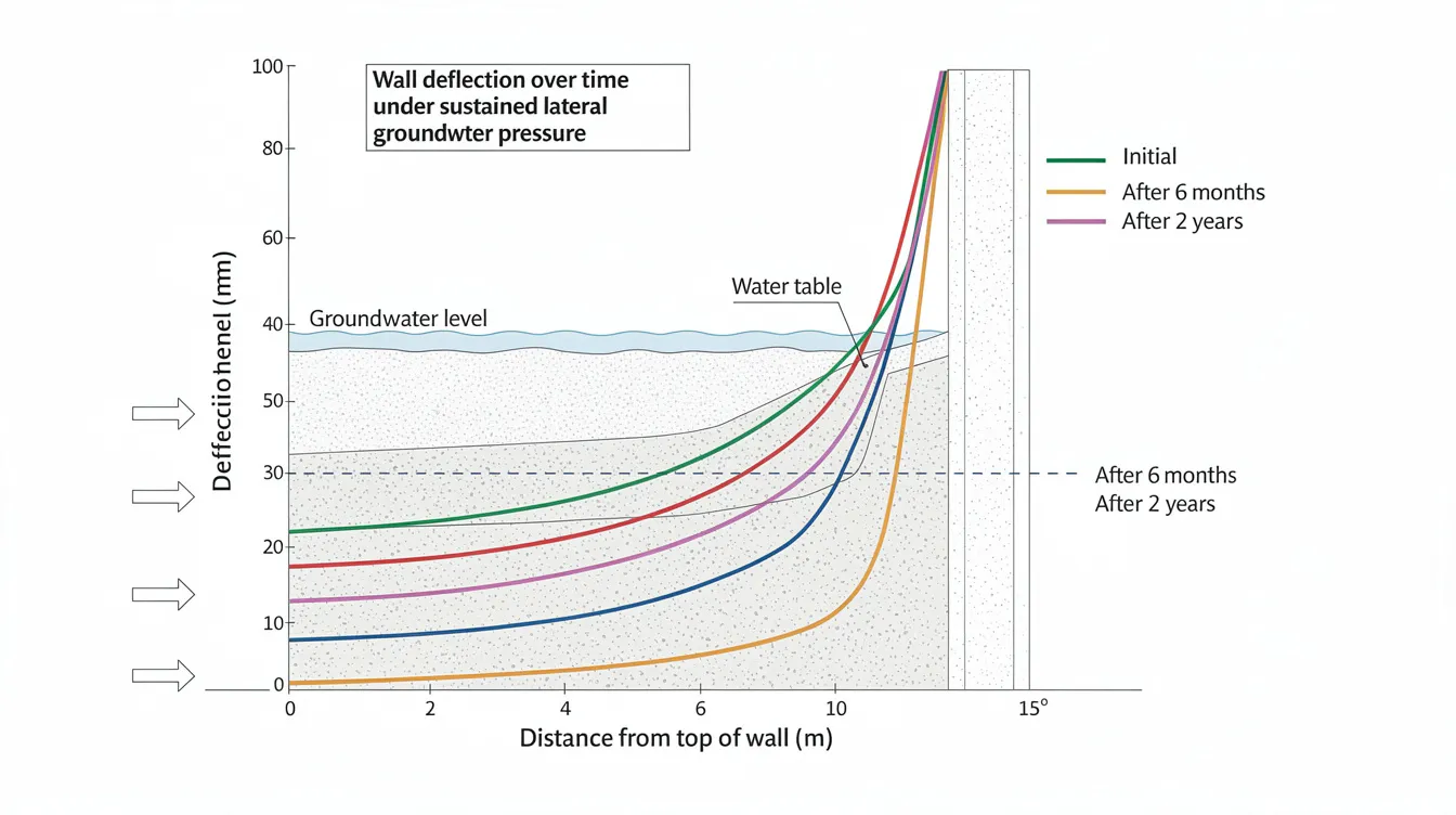
Concrete exhibits creep under sustained stress, causing gradual increase in wall deflection beyond the initial elastic response. The creep coefficient φ(t, t₀)-where t₀ is the age at loading-quantifies this additional deformation. For typical concrete grades used in basement construction (C30–C50) under tropical moist conditions with relative humidity exceeding 90%, creep coefficients of 2–4 over long durations are common. Structural engineers consider long-term concrete creep in design for below-grade structures because as creep accumulates, elastic deflection transitions into permanent geometric distortion.
Hydrostatic loading creates bending moments and tensile stresses in foundation walls, and the multiaxial stress state under hydrostatic conditions produces different creep behaviour compared to uniaxial loading. Research on concrete under hydrostatic stress shows specific creep strain at higher stress levels being approximately 1.17 times that at lower stress levels. A permanently damp basement wall usually experiences different creep behavior than a dry wall-tropical humidity keeps concrete near saturated condition, which reduces drying creep but increases overall moisture-related creep under sustained loads. Moisture condition affects concrete’s time-dependent deformation under sustained loading, and concrete’s effective stiffness changes as it creeps under sustained compressive stress.
Early age loading (applying hydrostatic load before concrete has fully matured) significantly increases long-term creep, making construction sequencing and timing of backfill and water table recovery critical design considerations.
Soil-Structure Interaction in Soft Clay Conditions
Singapore’s marine clay-part of the Kallang Formation-exhibits pronounced primary consolidation followed by secondary compression (creep) that continues indefinitely under constant effective stress. Upper Marine Clay typically has water content of 60–80%, plasticity index of 45–65%, and compression index (Cc) of 0.7–1.3. These properties cause ongoing settlement rates of 0.005–0.02 strain per log cycle of time, creating progressive changes in soil loads and lateral pressure on basement walls.
Research on soil parameters of the Kallang Formation and Old Alluvium demonstrates that the soft soil creep model (as implemented in PLAXIS) is the most appropriate constitutive model for marine clays in Singapore. As consolidation proceeds, effective stress in the soil behind the wall gradually increases while pore pressure dissipates-but the wall may simultaneously deform through its own creep, altering leakage paths and pressure distributions. This coupled soil-structure interaction means that neither the soil nor the structure can be analyzed in isolation for long term stability assessments.
Progressive Deterioration Mechanisms
Over a 50–100 year design life, several deterioration mechanisms compound the effects of sustained hydrostatic loading:
High hydrostatic pressure leads to microcracking in concrete as creep strains accumulate. Creep can amplify deformation after cracking even though it is not the original cause of the crack. Lateral hydrostatic loads can cause horizontal cracks in walls, and hydrostatic pressure can force water through cracks and construction joints along the path of least resistance, driving moisture migration into the concrete matrix. Hydrostatic pressure can lead to moisture infiltration through concrete cracks, creating pathways for chloride and sulfate attack on steel reinforcement. Sustained lateral loads on basement walls can cause bowing or cracking, and over time hydrostatic pressure can lead to significant structural damage.
Waterproofing membranes prevent water from seeping through foundation walls initially, but adhesion degrades under sustained hydrostatic load. Carbonation and chemical attack from marine groundwater accelerate waterproofing deterioration. Uplift pressure can lead to slab heave and floor distortion, changing the stress distribution in the entire wall system and potentially causing joint separation at wall-slab connections.
The critical insight for permanent basement design is that these mechanisms are interdependent: creep causes cracking, cracking enables water intrusion, water accelerates corrosion, corrosion reduces stiffness, and reduced stiffness increases creep deformation-a self-reinforcing cycle that demands explicit analytical treatment.
Engineering Analysis and ULS Modeling for Hydrostatic Pressure
Building on these creep mechanisms, robust engineering analysis must combine ULS groundwater modeling, buoyancy verification, and time-dependent deformation prediction to ensure the building’s foundation performs over its full design life. This analysis typically requires PE endorsement for civil and structural works and coordination with an accredited checker for deep basement submissions.
Groundwater Level Modeling Procedures
ULS groundwater modeling should be applied to every permanent basement project where the base slab sits more than 1 m below the existing water table. The following procedure ensures conservative yet rational design:
-
Establish 100-year return period groundwater levels from historical piezometric monitoring data spanning multiple years, incorporating seasonal extremes, tidal influence for coastal projects, storm surge events, and nearby reclamation effects. Where historical data is limited, adopt cautious upper-bound estimates per Eurocode 7 Clause 6.5.
-
Model seasonal fluctuations and tidal influences for coastal Singapore projects. Include PUB’s Code of Practice on Surface Water Drainage requirements for minimum platform and crest levels. For sites near the coast, tidal fluctuation can create cyclic loading that accelerates creep accumulation.
-
Calculate hydrostatic pressure distribution considering partial relief drain effectiveness. Model both fully undrained (no relief) and fully drained conditions, then adopt an intermediate assumption-typically 50–70% drainage effectiveness-for the permanent design case; the undrained case captures the full lateral loads imposed on basement walls when relief measures are ineffective. Hydrostatic pressure can exceed 4 psi at 10 feet depth; for a typical 15 m deep basement with groundwater at ground level, the pressure exerted at the base reaches approximately 147 kPa.
-
Apply partial safety factors per Eurocode 7 and Singapore standards for ultimate limit state design. Use γ = 1.35 for permanent groundwater pressure actions. Verify both HYD (hydraulic heave) and UPL (uplift/buoyancy) limit states explicitly.
Buoyancy and Uplift Calculations
Buoyancy checks verify that the stabilizing weight of the structure exceeds the destabilizing uplift force from groundwater pressure. The uplift pressure calculation is straightforward: P = γw × h, where h equals the worst-case groundwater head above the underside of the base slab. For a basement at 5 m depth with groundwater at ground level, uplift pressure is approximately 5 × 9.81 ≈ 49 kPa. Constant fluid pressure from groundwater creates sustained mechanical stress on below-grade concrete.
|
Parameter |
Drained Condition |
Undrained Condition |
|---|---|---|
|
Groundwater Level |
–2.0 m from ground level |
Ground level (worst case) |
|
Hydrostatic Pressure at 15 m depth |
~128 kN/m² |
~147 kN/m² |
|
Uplift Partial Factor (γG) |
1.0 (favourable) / 1.35 (unfavourable) |
1.35 (unfavourable) |
|
Stabilizing Resistance |
Slab weight + walls + overburden + side friction |
Slab weight + walls + tension piles |
|
Relief Drain Assumption |
50–70% effective |
0% (drains assumed non-functional) |
Engineers must ensure proper compaction of backfill above any ground slab to maximize overburden resistance. Stabilizing components include concrete slab and wall self-weight, superstructure dead loads, soil overburden, side wall friction, and any tension piles or ground anchors. For Singapore projects, LTA’s E/GD/09/106/A3 standard provides specific partial factor tables for various groundwater action combinations.
The Marina Bay Sands basement-a 16-hectare excavation averaging 18 m depth in reclaimed marine clay-used 1.5 m thick diaphragm walls and complex construction staging to manage both hydrostatic load and buoyancy during and after construction. A documented Singapore case study of a three-level basement employed pressure relief systems under the base slab combined with tension piles, designing for full groundwater level at ground surface for the permanent UPL condition.
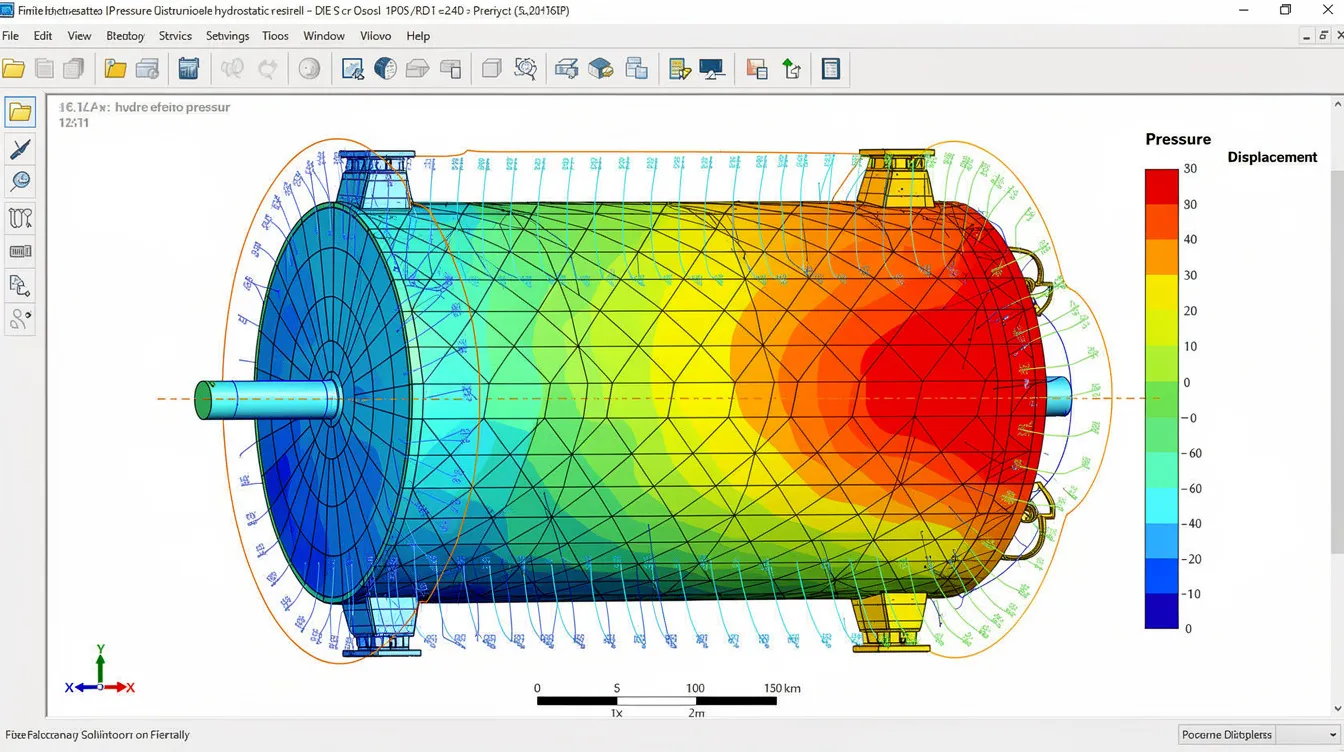
For creep analysis, finite element modeling using soft soil creep constitutive models (e.g., PLAXIS Soft Soil Creep) with locally calibrated parameters for the Kallang Formation provides the most reliable predictions of wall deflection over the design life. Recent advances include data-driven calibration using Gaussian Process Regression that accounts for age at loading, environmental humidity, and preloading history to reduce uncertainty in concrete creep predictions.
Common Design Challenges and Mitigation Strategies
Permanent basements in Singapore’s soil conditions face recurring challenges that, if unaddressed, compromise long term performance and the building envelope integrity. A thorough building defect investigation often reveals that common signs of failure trace back to inadequate consideration of the issues described below.
Inadequate Relief Drain Capacity
Relief drain systems frequently underperform over time due to clogging, sediment ingress, and reduced hydraulic gradient; when drains clog, groundwater pressure builds and can create the lateral loads the wall was supposed to relieve. Proper drainage requires designing redundant systems with at least 150% of nominal capacity, incorporating filter geotextile protection, and ensuring exterior access for maintenance and flushing. Backup sump pumps should be sized for tropical storm conditions. Where LTA railway protection zones are involved, pressure relief below base slabs may not be permitted, requiring the structure to resist full hydrostatic load without drainage assistance, with blocked drainage leaving water to follow the path of least resistance toward the basement wall. Proper grading ensures ground slopes away from buildings, helping prevent water from pooling near foundations and reducing surface runoff that recharges the water table adjacent to basement walls.
Underestimated Long-Term Groundwater Levels
Historical monitoring data may not reflect future conditions driven by sea level rise, land subsidence, or changes in surrounding development. Designers should apply climate change factors of 1.2–1.5 to historical groundwater data and conduct sensitivity analyses. Singapore’s projected sea level rise of 0.5–1.0 m over the next century directly raises the hydrostatic head for coastal projects. Professional assessment of groundwater levels should encompass at least 5–10 years of piezometric data where available, supplemented by regional hydrogeological models. Proper grading should slope away from buildings to reduce water accumulation near the building’s foundation.
Insufficient Creep Considerations in Design
Sustained hydrostatic pressure can significantly alter the stress-strain state of concrete and masonry foundation walls over time and force water into small defects, worsening creep-related damage, yet many designs treat loads as purely elastic. To prevent water-induced long term structural damage, specify enhanced concrete grades (minimum C40/50) with low water-cement ratios and dense aggregates, ensuring wall thickness provides adequate section depth for long-term creep resistance. Apply a minimum wall thickness factor of 1.3× for 100-year design life in tropical conditions. Use porous materials with care-drainage media must remain functional but concrete itself should have low permeability to stop water from penetrating the structure. Waterproofing systems should be rated for the full anticipated hydrostatic head, as water follows the path of least resistance at joints and tie holes if detailing is inadequate, with negative-side membranes applied at construction joints and tie holes to ensure basements remain dry. Regular periodic structural inspections can identify early common signs of creep-related distress before they compromise structural stability.
Changi Airport’s reclaimed land provides a cautionary example: soft clay layers up to 30 m thick experienced more than 3 m of settlement after filling and construction due to ongoing soft clay creep, despite extensive ground improvement with vertical drains and dynamic compaction.
Conclusion and Next Steps
Managing hydrostatic pressure and its associated creep effects in permanent basement walls requires an integrated approach to ULS groundwater modeling, relief drain design, buoyancy verification, and time-dependent material analysis. In Singapore’s soft marine clay conditions, where saturated soil maintains sustained groundwater pressure against retaining walls and foundation walls for the entire design life, neglecting any one of these interdependent factors risks progressive deterioration of structural integrity.
The key takeaway for building design teams is that hydrostatic load is not a static calculation solved once at design stage-it is a dynamic, evolving condition where drain effectiveness degrades, groundwater levels may rise with climate change, and both concrete and soil undergo creep that permanently alters the structure’s geometry and stress state.
Immediate next steps:
-
Conduct site-specific groundwater monitoring with piezometers over multiple seasons to establish reliable design water table levels
-
Engage a geotechnical specialist for soil-structure interaction analysis using soft soil creep models calibrated to local Kallang Formation parameters
-
Coordinate with BCA submission requirements for deep basement projects, including temporary works design for earth retaining systems during construction
Related topics worth exploring include advanced finite element modeling for complex basement geometries, integration of waterproofing systems with structural design for long term durability, and digital twin monitoring systems that validate design assumptions on groundwater levels, pressure relief performance, and creep deformation throughout the structure’s service life.
Additional Resources
-
Eurocode 7 (EN 1997-1) – Clauses on characteristic groundwater pressure determination and UPL/HYD limit state verification
-
Singapore SS 637:2018 – Basement waterproofing requirements including negative-side hydrostatic pressure resistance
-
LTA Code of Practice for Railway Protection – Restrictions on pressure relief systems near rail infrastructure
-
PUB Code of Practice on Surface Water Drainage – Minimum platform levels and flood design requirements affecting basement groundwater assumptions
-
ACI 209 / CEB-FIP Model Code – Concrete creep coefficient prediction models applicable to tropical environments
-
PLAXIS Soft Soil Creep Model – Constitutive model for time-dependent analysis of marine clay behaviour around deep basements